Sierra West Machine Shop
I'm really enjoying a build I am making for a friend of mine in O Scale, a scale which lies outside my model railroad realm of HO.

My friend, Doug Matheson, had built the two machines to the lower right as well as the boiler. He then asked me to complete the remaining machines, some of which you see here. In March, 2018, Doug and I co-presented a clinic for our local chapter of the NMRA, The St. Lawrence Division. Doug spoke to the overall workings of a machine shop and I spoke to the modeling of the machines.

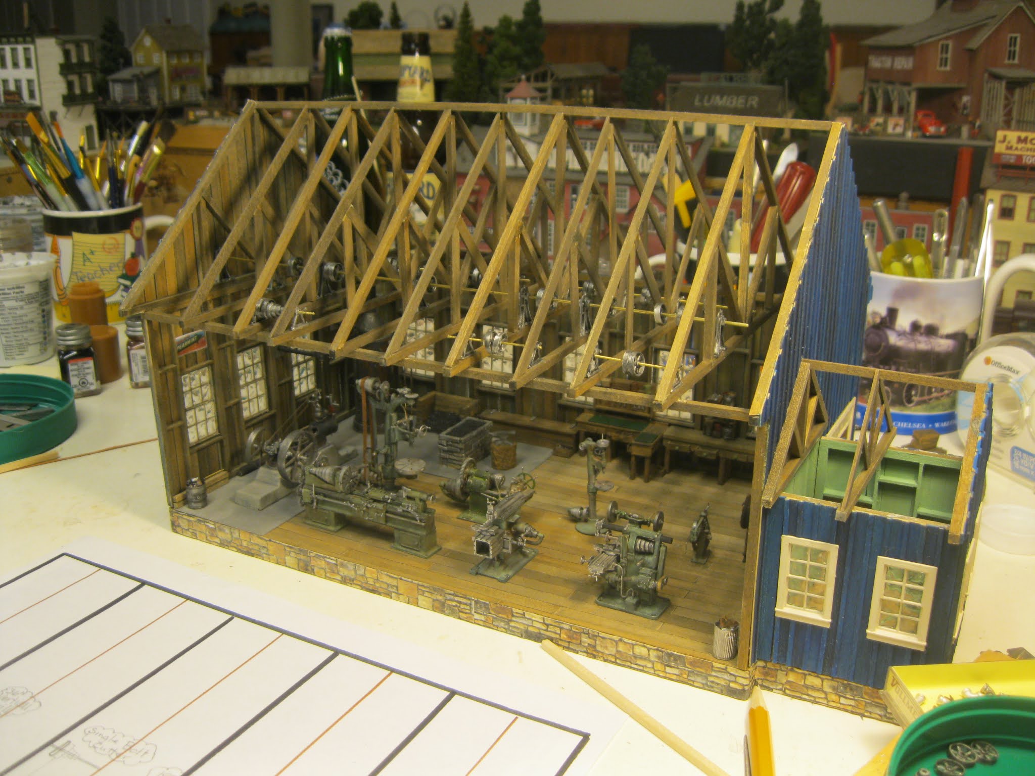
Here is my progress to date. All of the machines have been completed along with the shop engine and various scratch-built items necessary for the workings of a machine shop.
(You can enlarge all of the images by clicking on them and can return to the default look of the page by clicking outside them.)

While so much more must be done to finish the main shop building before the diorama can be built, this yet unfinished project is made up of many "totally completed" projects from each machine, the water tower, the joining of the shop engine to the boiler, the shop heater build as well as the vent for the hearth, to name but a few!
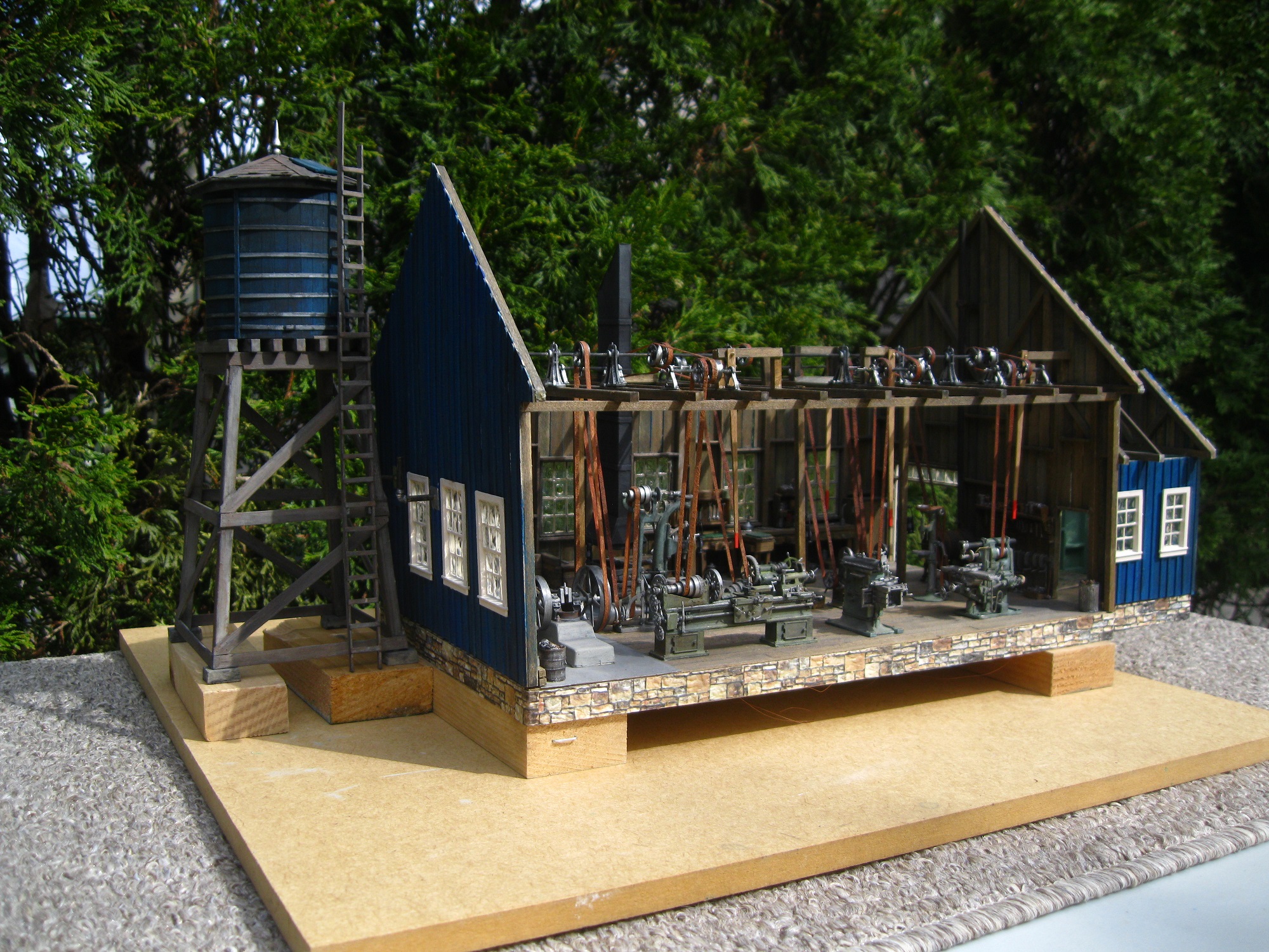
You may be wondering why the shop is elevated. I have wiring running from lanterns attached to the main posts in the shop. The hidden wires will run to a battery source hidden beneath the diorama base once time comes to create the base. The lanterns will be kerosene lit as Doug and I are setting the era in the early 1900's when electricity would not have serviced the shop in its rural Ontario setting as yet.

Water is required for the boiler which is then heated to operate the shop engine, thus a water tower is required. This model from B.T.S. fit the bill nicely. I only required 2/3 of the height so the legs and framing were shortened. The tower is painted in Prussian blue to match the shop...Doug's favourite colour.
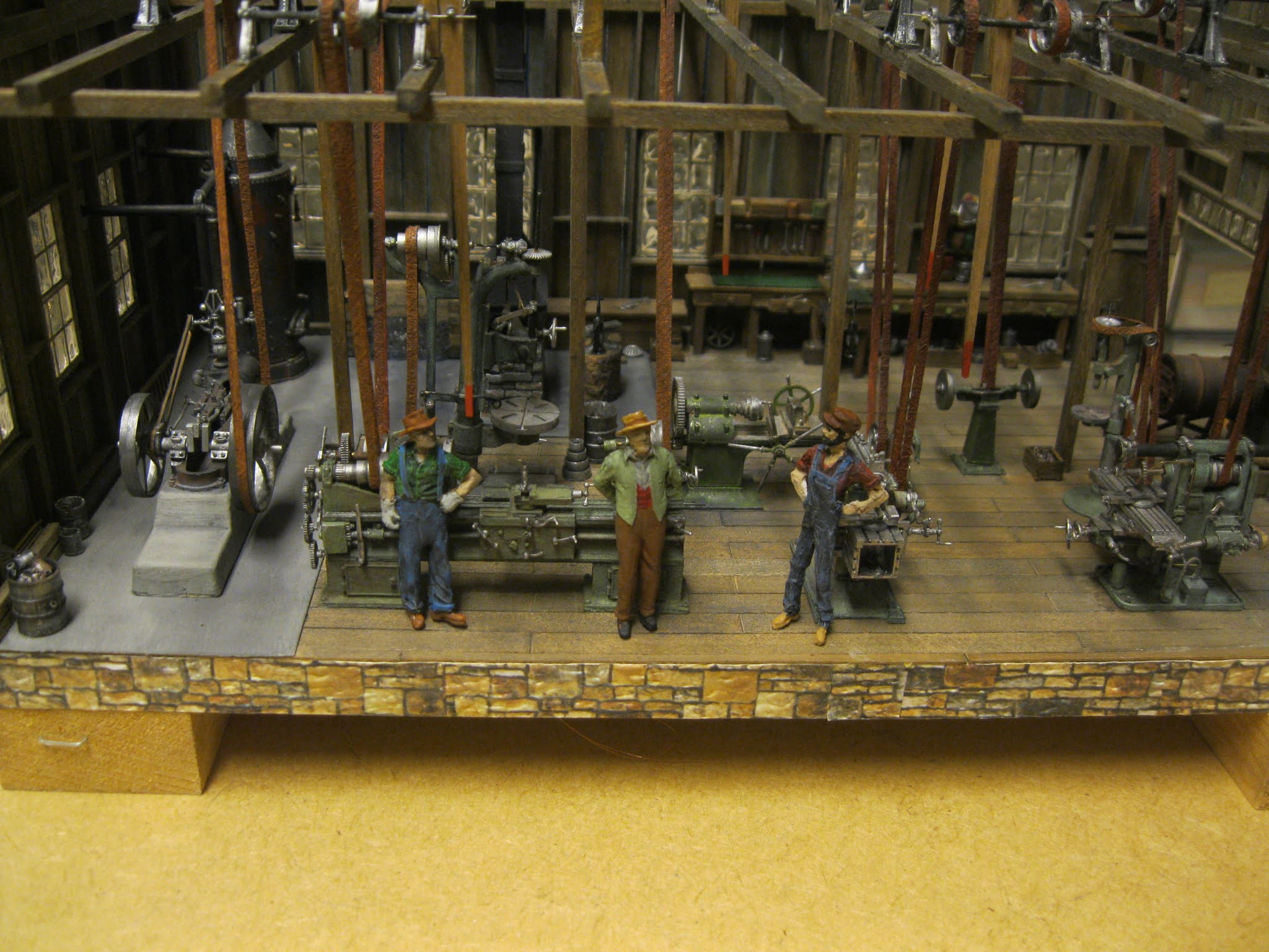
This picture showcases my most recent progress. Three O-scale figures have been painted and weathered and are momentarily leaning up against a couple of machines. This is but a temporary placement for the photographer. These three lads could end up anywhere in the shop or on the diorama.

Let's head back to the earlier stages of the project.
Here are the completed machines.
1. Single Bolt Cutter
2. Pedestal Grinder
3. 18" Drill Press
4. Power Hacksaw
5. 36" Vertical Drill
6. Shop Engine
7. Boiler
8. Crank Shaper
9. Universal Miller
10. 24" Engine Lathe

The instruction manual for all of the machines.

As I was unfamiliar with how these machines worked and knew very little about each part, I labelled each part in pencil even though a listing was given on the reverse side of this page for some of the machines in the grouping.

Research indicated that machines come in a variety of colours, some quite bold in fact. Doug and I settled on this standard sage green tone. I was sure to weather each machine as I went along with the build. This is the 24" engine lathe. The major function of an engine lathe is to change the size, shape or finish of a revolving work piece with various cutting tools.

Let's check out another machine.

The Universal Miller is made up of numerous components as are many of the machines. It machines custom parts to precise tolerances. It can drill, bore, cut gears and produce slots.

Even though it is O-scale, these machines are only slightly taller than an inch in height and they contain up to forty to fifty individual white metal parts! Even the main body of each machine is made up of various white metal component parts. We will examine the finished machines more closely later on.

Rust coloured PanPastels were used to weather the machines.

Followed by a wash of black acrylic paint.

Because the component parts are listed on the same page (or even opposite page) I am able to reference the parts more easily for the 36" Vertical Drill.


The crank shaper. It can generate straight and flat surfaces. It can smooth out rough surfaces.

It can make internal splines, dovetail slides and gear teeth. Here we see it weathered.

I've lined up the machines built so far. They are coming along!
The pedestal grinder on the far right is used to sharpen high-speed steel cutting tools used on the lathes and milling machines. It can debur, or remove surface imperfections.
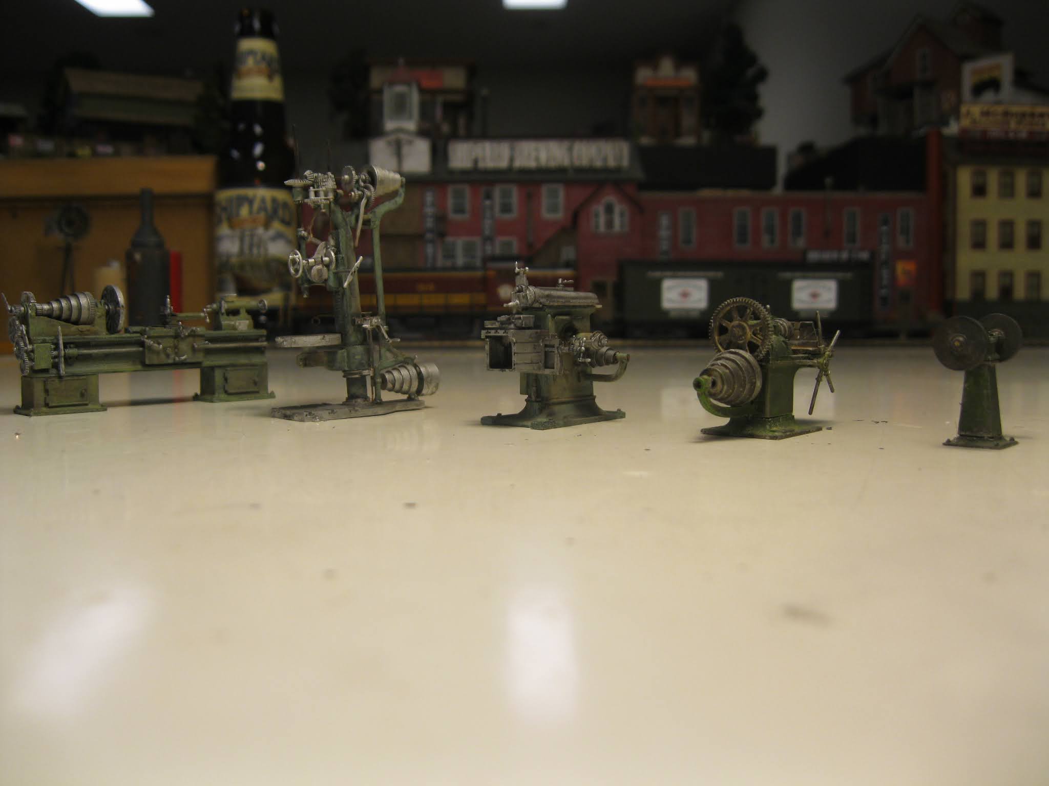
A lower view. The single bolt cutter, second from the right, can cut bolts, chains, padlocks, rebar and wire mesh.

The 18" Drill Press was a quick build. It is used to cut holes through metal, wood or other materials.

The Power Hacksaw completed the machines. It can cut large sections of metal. Using a reciprocating back and forth motion, it can cut material more efficiently than the cutting action of human hand using a hand saw.

The final component for me to build was the shop engine.

This was a joy for me as it makes a beautiful model and it was the final major component at the time of the build. It will receive belting later on.

Because I will be creating a diorama for Doug, it is essential to have numerous detail parts for the interior and exterior scenes. These were all either resin or white metal details which I painted, stained and washed using acrylics, Pan Pastels and various chalks. The level of detail in these Sierra West parts is outstanding! These were additional orders that did not come with the machines themselves.

Doug created the base from plywood incorporating the office space. He brought me the base and the large sheet for the stone foundation.

I cut and glued the stone foundation around the entire base.

The lovely foundation came from a company in Greece!

A fresh razor blade does the trick in trimming the foundation to match the level of the flooring.

Next step, staining the floorboards with various shades of furniture stain.
I call this my "Monster Tool" which was made for me by my good friend, Ron Newby. It's great for scribing grain lines along the wall and floor board sections. When you offer up a "wash" following staining, the grain in the wood "pops" out nicely!

Saman's "Golden Wheat" furniture stain does the trick!
(I would use a similar colour tone, Saman's "Colonial" for the wall boards of the shop.)

A wash of acrylic black helps to weather the boards nicely.

Application time.

Those floorboards are looking mighty nice!

Done...as seen under incandescent lighting.

My trusty weights placed atop the flooring overnight will ensure great adhesion!

The completed floor as seen under fluorescent Daylight Ultra lighting with the machines temporarily in position.

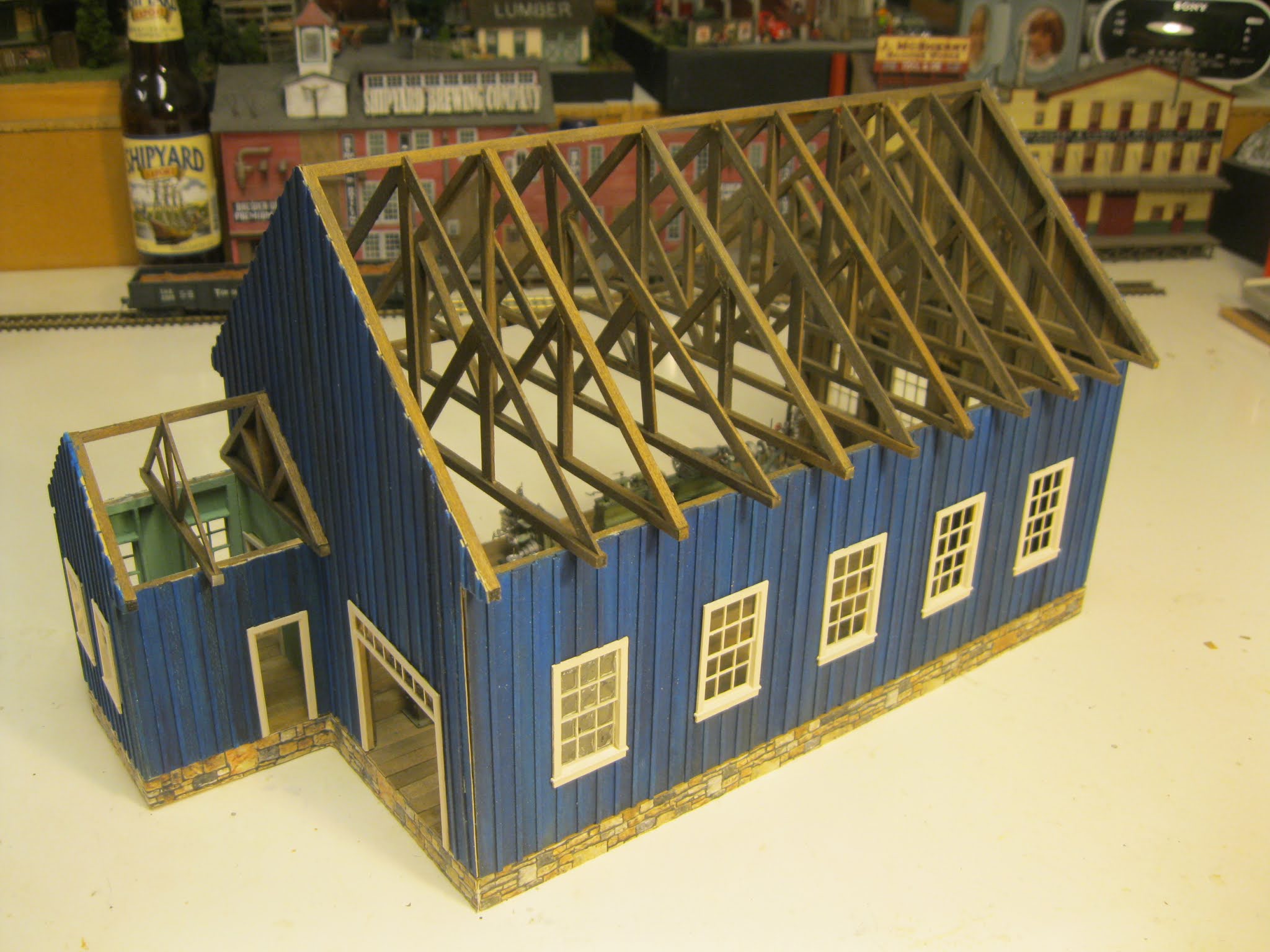
The main shop building does not come with the kit either. It's your job to create it from scratch. Doug and I determined an appropriate size for the shop. I built the walls as per the drawings Doug designed using Mount Albert Scale Lumber offered by Fast Tracks.

Window placement and roof pitch must be taken into consideration. This far wall segment will attach with other wall assemblies (note the squiggly line indicating this board will come from elsewhere). I created this wall drawing based on the long wall dimensions Doug had come up with.

The wall boards have been cut to length and have been doctored with a similar furniture stain to the floors and the wash of acrylic black.

The other side of the wall boards are lined up and ready to be placed on the wall sections.

The wall boards are going in and the battens are slowly covering the creases between the uprights.

A look from the interior shows the nicely stained wall boards which are blue in colour outside the building.

Cuts in the board are made to accommodate the windows.

The blue is very attractive, but I will tone it down further at a later time.

I stand the wall up in front of the machines.

This gives me a nice feel for how things will look later on.

The boards have been given a wash of the Prussian blue and further stained for weathering. No battens as yet, but it's a good time to test the window fit!

The Prussion blue was added to walls in a series of washes until I achieved the desired look I was searching for.

The end wall takes shape.

And...the other end wall where the office will jut out.

The battens are going in and will require further washes of blue and then weathering.

The structure for the office takes into consideration the roof line as the battens are cut shorter to accommodate the roof.

The office area with a doorway that leads to the machine shop.

The template I designed allows me to complete the end wall of the office area.

Test fit of the windows. Don't worry...wall sections will frame the windows on all sides.

I had to cut off the base footplate of the Grandt Line door to match the bottom of the office wall. This doorway will lead out to a loading dock eventually.

Here is the doorway that leads outdoors to an eventual loading dock.

A peak inside the building!

Previous to the test fit I scrubbed all of the windows and door trim with resin prep and then rinsed to ensure paint would adhere to the parts.

A very light shade of tan called fawn was employed on the window and door trims.

The door section goes in. I am measuring its width for Doug so I can notify him of an appropriate width for a sign which he will create for above the doorway.

Doug and I really wanted to keep those nice looking windows up top the door opening. This was a tricky project as the original Grandt Line doorway was wider so I had to make a cut in the center and then re-align the window area up top. Kristal Clear filled the openings nicely. Note the areas for the hinges I have created.

Time to scratch build the doors.

Voila! Done in no time at all.

Adding a few hinges.

This image shows the doors opening into the building. They are just temporarily standing in place. I would later change their opening to the great outdoors instead.

Temporary placement of two wall sections allow me to see if any modifications are required. With careful planning and devotion to detail, none are!

I've "tac glued" the wall sections in place momentarily to show me how the overall structure will look. Yes, the outer wall is leaning at the moment...no problem!

This "pre-Covid" image was taken at my workbench. This is my buddy, Doug. I wanted him to come over and approve my placement of the machines on the drawing of the shop floor.

We are happy with the location of all machines, the boiler and the shop engine.

Let's examine the far end wall, the one without the office.
Doug and I have decided on a 22" overhang. I actually created a couple of other drawings similar to the one above, each with a differing overhang length and 22" won out!

Once again, placement of the wall board where a sharp razor blade will cut the angled end at the roof's edge.

The interior wall look.

The exterior wall look...with further weathering required.

As I am proceeding throughout the build, I constantly "shore things up" to give me the illusion of how the developments will look later on.

As mentioned a few times, I've put a tiny drop of glue on the wall sections to allow them to stand up on the main floor base.

I'm starting to see how the machines will appear with a nice wooden walled backdrop along two walls!

To create the rafters, I gently lay the boards atop an end wall. There has to be a "notch" at the peak of all of the rafters to allow the main roof beam to run along the building's peak between each rafter section. Once I am satisfied with the look, I will glue one rafter together then use it to create a drawing template for all of the other rafters.

One rafter created.

I begin mass producing the rafters which, of course, must match the roof line of the two end walls. I stack them as I go. A total of nine will be required with "every other" rafter being thinner.
I've "raised" the rafters, but they will need to be "razed" in order to add the miscellaneous details up top the rafter footings. These parts will include the bearings for the main drive shafts and counter shafts.

At least, I give myself a lovely indication of how the general "overall" look will be with the rafters eventually in place.

The rafter sections have been "razed" but kept in good working order as they will now allow me to determine the placement of all of the shafts, bearings and pulleys which must be strategically placed above their respective machines located below on the shop floor.

As we've learned, Doug ordered some added detail parts instrumental in creating the atmospheric setting of the running of a machine shop.

Following a wash and rinse of Resin Prep, it was time to paint.

Some of the items.

A cabinet.

A bench (under different lighting).

A wall mounted shelf.

The hearth for the blacksmith area.

I had some leftover coal I had used to fill hopper cars, so I scrunched it down to a more suitable size.

It looks nice in the hearth.

I scratched a coal bin that you will see in place later.

I was hesitant about the windows. I couldn't simply put a plate of glass or clear plastic in behind the muntin bars due to the fact that the window panes must appear "between" the bars from both sides of the wall...the exterior and the interior. My good friend, Bill Meek, had some leftover Micro Kristal Klear which I couldn't find as the shops were now shut due to Covid restrictions.

My reservations weren't realized as the Kristal Klear actually was able to spread across the wider openings of the O-scale window panes! Notice the newly painted detail items such as shelves, cabinets and table tops. I built from scratch some legs for the tables and desk work areas.

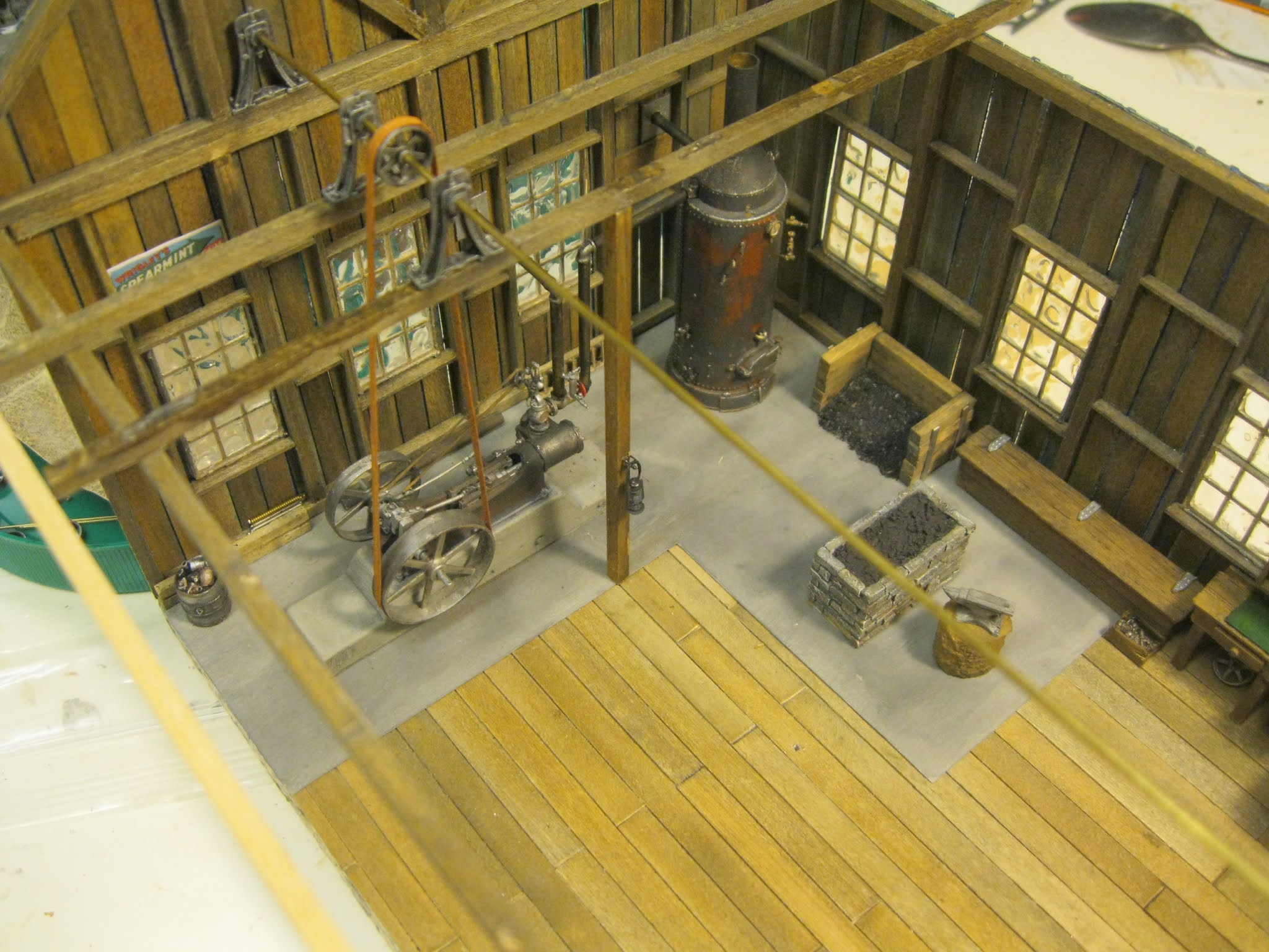
We felt that the shop engine and boiler should rest atop a concrete pad.

A thin piece of styrene was painted grey and weathered with black before installation.

The shop heater was a mini-kit created from a series of white metal castings. C-clamps and more wall mounted units add to the scene. In this early stage, some of the details may change their locations as the build progresses.

Many of the detail items now painted.

This previously shown image showcases more of the exquisite high caliber items I have painted and weathered that come from the magic of Sierra West.

This image shows the hearth with anvil on a log as well as the scratchbuilt coal bin. I've added some browns to the grey stone hearth to bring out more colour. Notice, too, all of the piping which exists between the shop engine and the boiler as well as the piping leading to the great outdoors from both items. This was a highly detailed and delicate aspect of the build...quite daunting in fact! I chose to join the two items "outside" the machine shop on my workbench for ease of construction.

This earlier image shows some of the piping resting temporarily in place yet painted and weathered.

The only feasible option...working away from the shop floor.

To allow the elbows to fit within the various piping, some inside filing was required.

Then the two items were twinned for life.

I had to gently "tuck" the two conjoined pieces back into place on the machine shop floor.

As seen in different lighting.

Indeed, the routing of the pipes was the most challenging aspect of the build thus far.

This "mini-project" took two full days of modeling time to get things right...lots of trial and error here!

While looking for an item on my storage shelves I came across this casting in HO scale which matched closely in size one of the castings from Sierra West's O scale offerings.

Why not make use of it seeing as it is extraneous to my own modeling needs!

It fit like a glove along the righthand wall near to the office door!

A closer look at the newly painted and weathered shelf along the far wall. The shop is coming along...slowly!

This expanded view shows me that the shop will look busy when it is eventually completed!

We check out the arrangement of items.

Looking good so far!

Slightly different lighting.

The next phase is determining where the support posts for "every other" rafter footing will go.

This is a crucial step as I will be attaching "kerosene lanterns" to the posts that will have wiring recessed into the back of each post so as not to be seen. The wiring will run down through the flooring, thus, the exact location must be noted for the drilling of each hole so the wires can reach a hidden battery or power source beneath the shop floor.

I realized that the best way to determine the location for the hole would be to extend a post down from the rafter. I created this temporary jig over the rafter's center upright which offers up the exact location of the support post.

In doing so, I was able to make a marking on the floor in pencil.

I felt like a crafty lad in figuring out this method! Big grin!

The view from the other angle. The long rod will be the central drive shaft, also called the main drive shaft.

Doug had loaned me a book on how machine shops work. In the diagram above, the shop engine is simply an electrical one and is situated to the far right and numbered as object #13. When the motor powers up, it spins the lengthy main drive shaft. Belted pulleys off the main shaft extend out over the various machines and attach to their "counter shafts" high up in the rafters. On each countershaft is three pulleys. One spins freely of the countershaft. When the belt is on that pulley, it simply spins and the countershaft does not. To engage the countershaft, a worker moves a long wooden stick called a "belt shifter" or "belt striker" which is located on a fulcrum up above. When the employee bats the stick (usually with a gloved hand) the belt shifts over to the pulley that is firmly attached to the countershaft thus engaging the shaft to spin. A third pulley also attached firmly to the countershaft and belted to the machine down below begins to spin and the machine comes to life!

Time to get down to weathering the pulleys and bearings.

The larger bearings which I chose to use for the central drive shaft are a grey plastic. I first painted them black and then dry brushed silver to gain an aged look.

To prepare them for the main drive shaft I first had to ream out the accommodating hole.

A test fit!

All is well.

Then a test "look" to see how they will work out up in the rafters. I have only placed half of the rafters for the test.

Looking good though!

As for the rafters, I had to ensure the main beam at the peak would line up. This was my way of checking.

I realized that the 36" vertical drill required a main belt.

I decided to use the same material for this belt as the material for all of the main belts.

I determined the width of the belt and drew lines down the backside of the material.

Doug and I ruminated for a while as to which material to use for the belting. He found somewhere on the internet that Tyvek would be advisable due to the fact it will not warp over time after being painted and exposed to varying conditions of humidity we have in our northern climate.

One side has a rougher appearance.

I chose Burnt Sienna to give a "look of leather" to the belting. I will eventually weather all of the belts with a black acrylic wash.

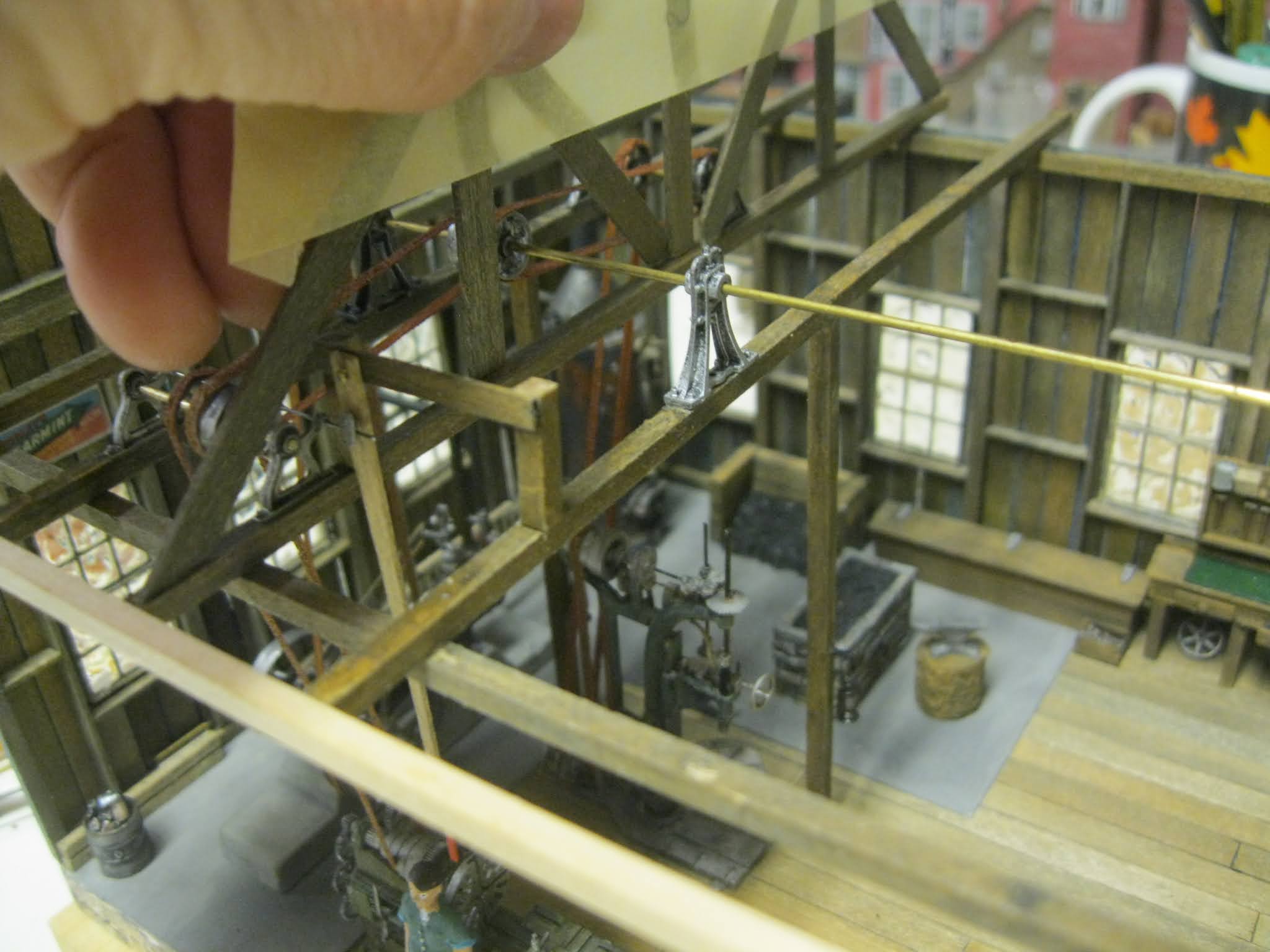
This image showcases the first support post in place and you can see the lantern hanging off a support attached to the post about a third of the way up. Doug and I determined the height where the lantern should hang based on the reach of an O-scale human figure. Note how the main drive shaft is now in place with three bearings supporting it above the rafters. Note, as well, the belt running from the shop engine up to the drive shaft.

Doug purchased the O-scale lanterns from GLX Enterprises, a local manufacturer up here in Ottawa owned by our good friend, Gilbert Lacroix.

And...here is one of my many railroad lanterns! I raised it as high as I could to calculate a desired height to see if it would match up with the distance Doug and I had settled on and it did! I was pleased!

To hide the wiring, I use a tiny awl to create a recessed strip along the rear side of the post.

No one will even see this side.

The wiring and bulb has been placed inside the lantern.

The illusion is that it is a kerosene lantern and not powered by electricity.

Once the wiring is glued into place, I hide it with paint. The paint will be weathered to look like the surrounding wood on the post.

Meanwhile, up top the rafters I will have to scratch build the full countershaft assembly for each machine. Yikes! Note the two belt guides on the smaller rod. I've had to drill them out with a fine drill bit. I purposely placed the guides upright to show you them. They will be removed and placed on the rod facing downwards.

The pulleys have been bored out and I have drilled out the small holes in the bearing to accept the rod for the belt guides. This rod comes from some leftover guitar strings.

Here I am drilling out the tiny hole where a rod must penetrate.

I have mapped out the placement of the countershafts machines.

Aha! Here is an image I found of one of the countershaft assemblies where I have now rearranged the belt guides to hang low toward the underside of the double pulley section.
Each of these assemblies took considerable time and patience to complete from scratch and each machine required one!

Then I created this mockup (image shown previously).

I have simply rested each countershaft apparatus where it should be located taking care to observe the location of the rafter uprights and angled support sections.

Aerial view.

Side view.

Then I brought the rafter assembly over to the structure.

This provides yet another idea of how things will appear in the near future.

A view from ground level.

I am pleased with the look.

And...most importantly...the countershafts locate themselves where they should be!
Looks impressive in my books!

I once again remove the rafters from their footings while masking tape keeps their structure together.
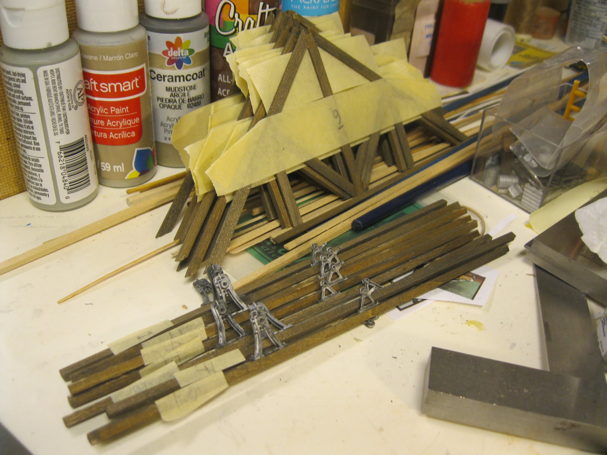
I have labelled the rafters and footings so they will be matched together when reassembled.

The first rafter footing goes in place. I placed a bearing over top the shop engine as well as one along the end wall to hold the main shaft. I have also glued a "fake" piece of wood along the front of the eaves. This length of wood will act as a guide for all of the rafter footings to line up properly. It will later be removed.

The engine will be the first item strapped to the main drive shaft which is appropriate in my books. The leathered appearance of the belts matches the colours perfectly with so many belts I have seen in my research. Again, I will provide a wash of black acrylics to these belts later on in the process.

I glue the next rafter beam (footing) in place and line up the first support post using a small T-square.
The post is now in along with the lantern. The shop engine can now begin rotating the central drive shaft! Hehehe!

Another look.

The first machine placed in the shop is the 36" vertical drill. Because it has a "belt shifter" designed within the body of the machine, a belt shifter is "not" required up top. Therefore, we only require two pulleys up top.

The belt shifter is located low down near floor level on the drill.

A view in different lighting.

As just mentioned, the belt shifter can be seen at the lower left of the vertical drill.

I wanted to take a step back to share with you the wiring leaving the post and entering the pre-determined hole in the flooring.

Again, in different lighting.

The next couple of rafter footings go in and my T-squares act as weights to allow the glue to set.

The lantern is easy to spot on the post.

A better shot.

Another low angle view.

I must be very careful to determine the location of bearings, shafts and supports as I move along up top. The second machine to go in place is the 24" engine lathe where you see the O-scale figure down below. This machine requires a belt shifter up top, so the wooden supports must go in place to support the apparatus.

A closer look at the wooden support with the belt striker in place. Note too that there are three pulleys along the countershaft as the machine below does not have a belt shifter attached to it...therefore the belt shifter must go up top.

The gentleman O-scale figure could easily reach up and move the belt with the wooden shifter. This gentleman will not end up working in the shop as he does not wear the appropriate clothing. He will be repainted and weathered eventually.

For safely, the tip of the belt striker is painted red.

Another look.
As I worked along, I constantly checked all structural work for clearance using one of the rafter assemblies.

Designing and building the support for the belt striker.

Attaching the striker to the support.

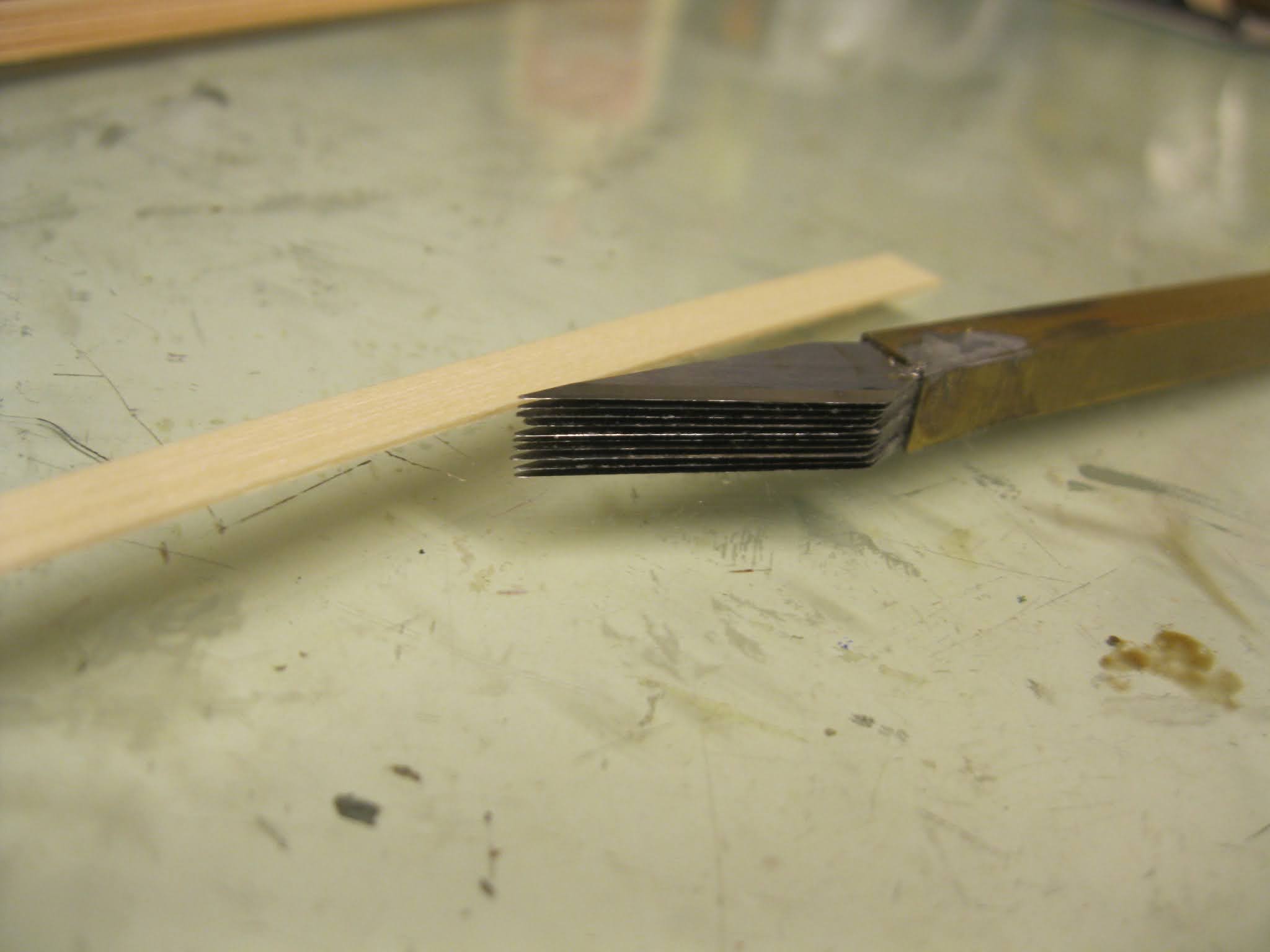
The belt strikers are simple to make. I simply drew a diagonal line down a pre-measured length of stripwood then used a razor blade to create two strikers from one strip of wood.

It's pretty tricky working each belt from the machines up to the rafters. This was an aspect of the build that I fretted over for some time. I came to the realization that I should wrap the belt around "the pulley on the machine" first and glue it in place on the machine. Then I would glue the machine to the shop floor. This would allow me to bring up both lengths of belting and superglue it to the pulley taking care to have the cut hidden along the back of the pulley so as to not be seen. I took great care to ensure the "join" would line up nicely.

Here is a look at the entire countershaft assembly which was made "off site" on my workbench, then transported up into the rafters.

The belt striker is in place for this countershaft. The fulcrum is located where the rod attaches to the striker and the anchor is up above.

We follow along as I have now placed the third machine on the shop floor and attached it to its belts. The single bolt cutter is one of the two machines Doug had built before he asked me to take over the task of building the others.

A "side on" view in the yellow incandescent lighting.

A shot from afar. Note the fake piece of lumber that simply acts as a guide for the rafter footings.

Small clamps always come in handy when you are a scratchbuilder! This one is ensuring the rafter footing will remain attached to the upper wall beam. This long wall will remain un-modelled to offer the viewer the chance to see inside the machine shop.

Yet another view showing how I have begun darkening the belts slightly with washes.

The shop heater required a small box to hold wood that has been cut for fuel. This creative scratchbuild took all of fifteen minutes...one of the easiest aspects of the project thus far!

It's in its place on the floor beside the shop heater.

The shop heater came with piping not long enough for our needs. The entire kit was made up of white metal parts. I wanted to create an extension up through the roof and I found some basswood doweling that had the same dimensions. Careful painting and weathering created a perfect match.

I'm attaching the pipe to the end wall.

I angled the top of the pipe to fit just below the roof line. Seeing as the eventual roof will be removeable, I didn't want the pipe to go up through a hole in the roof as it could easily be disturbed and broken in the removing process. Rather, I truncated it at the roof line and will firmly attach its upper part to the top of the roof itself! Now that's thinking!

Three of the smaller machines along the back row will share the same countershaft, a longer one than the others. The whole assembly has been temporarily designed but not glued down as yet, just to provide me with the opportunity to check out if all items are in their proper location. (Ignore those "drunk" pulleys...they aren't glued in place!)

The fourth and final support post is going in with its lantern already attached and the wiring for the "kerosene" already sent down through a tiny hole in the floor.

That trusty clamp comes into service once again making sure the top of the post lines up with the rafter beam.

My well-appreciated mini-squares ensure the post is perfectly perpendicular to the floor in all directions.

The three smaller machines go in at the back with their belts already attached. These are the power hacksaw, the pedestal grinder (the other machine Doug had built) and the 18" drill press.

Looking good so far.

A few different angled shots.

Yes, it must look to you like a maze at times. I must admit, I felt like I was walking through a maze when I went to bed each night and my dreams brought me back to the machine shop build! Big grin!

Showing the process of supergluing the Tyvek belting to the upper pulley.

Phew, they are all in!

I've removed the fake section of basswood that acted as a stop guide for the rafter beams.

In machine shops, oftentimes the countershafts cannot be located directly above the machine they are meant to assist due to hindrances in the rafters, beam supports, etc. This means that many belts head up to the rafters from the floor at an angle as evidenced in this photograph.

In different lighting, note again the angled belting for some of the machines.

The O-scale shop is coming together.

It rests on the wooden blocks so as not to damage the wiring from the lanterns.

As mentioned earlier, their battery source will be located below the diorama base.

Every now and then I would take a break to work on the odd detail, such as this garbage can.

Using a white board as a background, we can focus on the shop only.

While I try to keep a neat and tidy workbench, sometimes it can become very cluttered in the middle of a project!

Tony Koester from Model Railroader Magazine once visited my layout and was impressed with how neat my workbench was. In fact he told me that when he is deep in the throes of project he may have but four square inches in which to work at his bench! We enjoyed a lovely visit!

Note the belt strikers with the red paint for safety.

There's one of those garbage cans in the corner.

A view across the floor.

Of course, the location of the pulleys on the machines themselves determined the juxtaposition of the machine on the shop floor in relation to the shafts above.

I'm happy with the results, although there is still lots to do!

An aerial view.

This sideways view shows the work up in the rafters, although it will be a while before the actual rafters go back in.

The piping outside the building to the left is for the machine engine exhaust as well as another pipe in back to bring water from the eventual water tower. Yet another lower pipe will be required to pierce the outer wall lower down from the boiler.
Remember our nice blacksmith's hearth? Well, it needs a hood to vent the rising heat to the great out of doors.

Seeing as we were under Covid-19 restrictions up here in Ottawa, the local hobby shops were closed and I only had a small amount of thin styrene remaining in my supplies.

Seeing as I didn't want to waste any of the styrene stock in error, I chose to design and build a "mock-up" of the hearth vent from cardboard first.

I measured the hearth and from these dimensions I began.

The lower section of the hood.

The valence is added.

Then the vent stack. I chose a rectangular appearance as I liked the look.

The angle adheres to the roof angle. Just as I had done with the shop heater venting, I didn't want the actual stack to "pierce" the roof where it could be damaged whenever the roof was removed. The vent reaches only to the roof from the inside. I will re-create the outside section of the vent and will firmly attach it to the outer roof when the time comes. To the observer, the two vent sections will look "as one" when the roof is in place atop the machine shop! I'm a crafty lad!

Time to build it with my very limited supply of thin styrene.

My square ensures proper 90 degree alignment.

Note the basswood in the interior of the vent which offers support.

Looking good!

The lowered flared section is being scratched.

Coming along!

Strapping ensures stability and my square ensures a right angle!

The finished product pre-painting and weathering.

I'm happy with the results.

Standing tall and proud.

Let's check the fit.

Lovely!

My tweezers help me hold the entire piece for painting.

The two wooden sections ensure the vent will be able to attach to the rafter beams, otherwise it would fall away and crash on the hearth. Yes, it must hang from above. I have placed a small buffer between the wood and the potentially hot vent.

The vent towers above the rafter beams.

It is adhered to beams on either side.

A look through the shop main doors.

The vent and hood can be seen way off in the background.

As seen from above.

Through the doorway again.

With the roof in place.

In different lighting.

The roof is mocked up.

Doug and I have decided to truncate the roof about an inch from the peak on the viewer's side.

This will allow maximum viewing of the interior of the shop.

Yet the roof will be removeable for total interior viewing.

A few outdoor shots.

It's coming along!

Before I tackle the roof, Doug has ordered other items for the diorama.

The B.T.S. McCabe Shop water tank will provide water for the shop boiler.

Here I am going away from scratchbuilding and heading back to kit building for a little while, but I don't mind...I enjoy both aspects of the hobby.

The kit contents.

No, I won't be staining the wall boards as yet, but I do require the stain bottle for another purpose.

Instructions indicate that the walls must be placed in water for a few minutes.

Then they are to be removed and placed around a small diameter bottle or jar.

To help Doug determine the height he wants for the water tower, I simply placed the unfinished upper section on some old VHS tapes (remember those?) until the desire height was met.

Let's create that upper section, shall we!

Fits like a glove!

The underbase that will fit snuggly in place.

Assembling the roof structure.

At the wedding altar!

Newly married!

Still more marriages to go!

Forming up nicely.

My trusty scratch tool that my good friend, Ron Newby, made for me. This will add grain to the wooden legs.

Doug has asked that the tower be painted the same blue as the machine shop with grey legs and roof, a nice colour combination.

The roof shingles are going down!

I pre-painted and weathered them.

Consideration for the roof hatch must be observed.

The ladders required assembly and further painting.

Done...weathered legs and all!

It look so cool.

I actually truncated the tower to two-thirds its height to match the desired appearance beside the shop.

At a later time, I will share with you this project build Doug had recommended for the diorama.

We are setting the diorama in the early 1900's, so I created this model in O-scale from Berkshire Valley Models for Doug.

I learned a great deal about horses from a friend in Toronto as I was making my way through the build. They must have shiny fur if they are to be represented as "healthy" horses.

I also built this model, the REO box truck, another kit from Berkshire Valley Models in O-scale.

REO stands for Ransom E. Olds, originator of the Oldsmobile company.

Some of you may recall a rock and roll band called REO Speedwagon. Well, I learned that the REO Speedwagon brought out by this company is the precursor to today's pick-up truck. You learn something new every day!

Keep checking in as I will be adding to this blog entry as the work progresses over time.

This is certainly one of the most challenging endeavours I have undertaken in my modelling life and I am thoroughly enjoying the process.

I recommend to anyone the idea of building a model in a scale outside the one you are used to and I would like to thank my good friend, Doug, for asking me to build this machine shop for him!

Time to paint up some O-scale figures from Rusty Rail.

This one was sent "gratis" with Doug's order.

I painted the skin a flesh tone and then painted all of the clothing black. Next step was to "dry brush" over the balc with white paint to allow the details to "pop".

Layers of paint washes were applied over the clothing in the desired colours. I didn't follow the procedure for the gentleman on the right as he is the shop proprietor and wears more formal attire.

I realized this lad was pretty tall, seven feet in fact! Well, the drummer in my band is almost that tall, but I may cut this lad down a bit or hide him somewhere in the back of the machine shop. I will also tone down the muscles in his arm with some sanding and filing and repaint the arm a touch.

For the time being I have rested the trio up against the machines to provide me with a "look" of how things will appear with figures in the scene.

They won't remain in this location as they are obscuring the amazing detail on some of the machines.

They will certainly find a home on the diormama at some point in time.

With these three in picture, the machine shop is "coming to life!"

I'm totally enjoying my retirement following a 40 year teaching career.
With the pandemic, I couldn't have picked a better to to make the break. I now have time to pursue all of my dozen hobbies with gusto and pleasure!
Remember to keep checking in on the progress of my Sierra West Machine Shop build
All the best, Mike Hamer, Ottawa, Ontario, Canada