Log Dump For the Sierra West Sawmill
This blog entry acts as an update on our sawmill build.
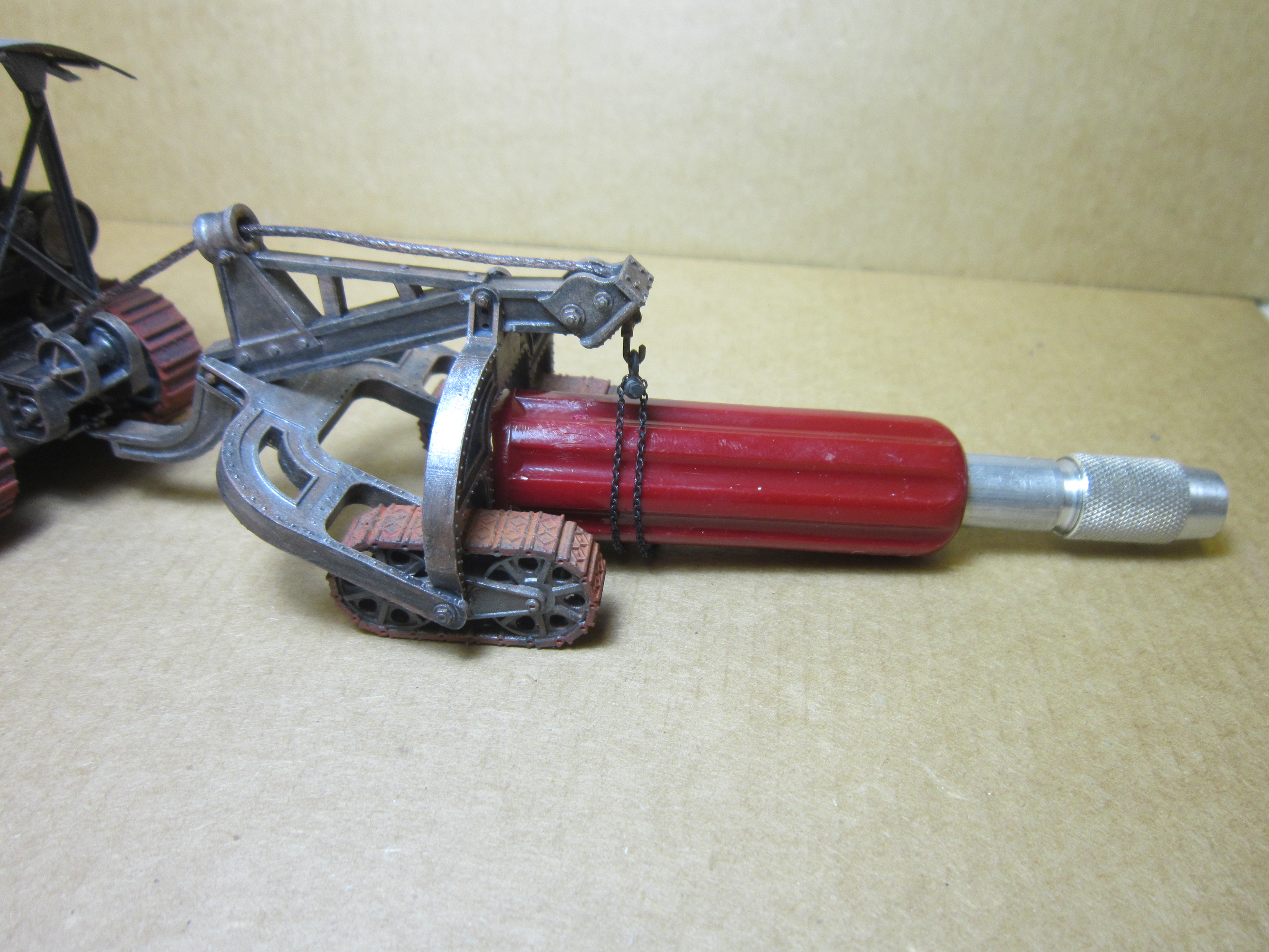
My good friend, Rob Kazakoff, came on board and created the wonderful stiff leg derrick you see in the image below - which Rob took.
The diorama has been out to two public displays already and will be in attendance at the next local NMRA meeting here in Ottawa.
This shot was snapped outdoors on Doug's property near the Rideau River south of Ottawa.
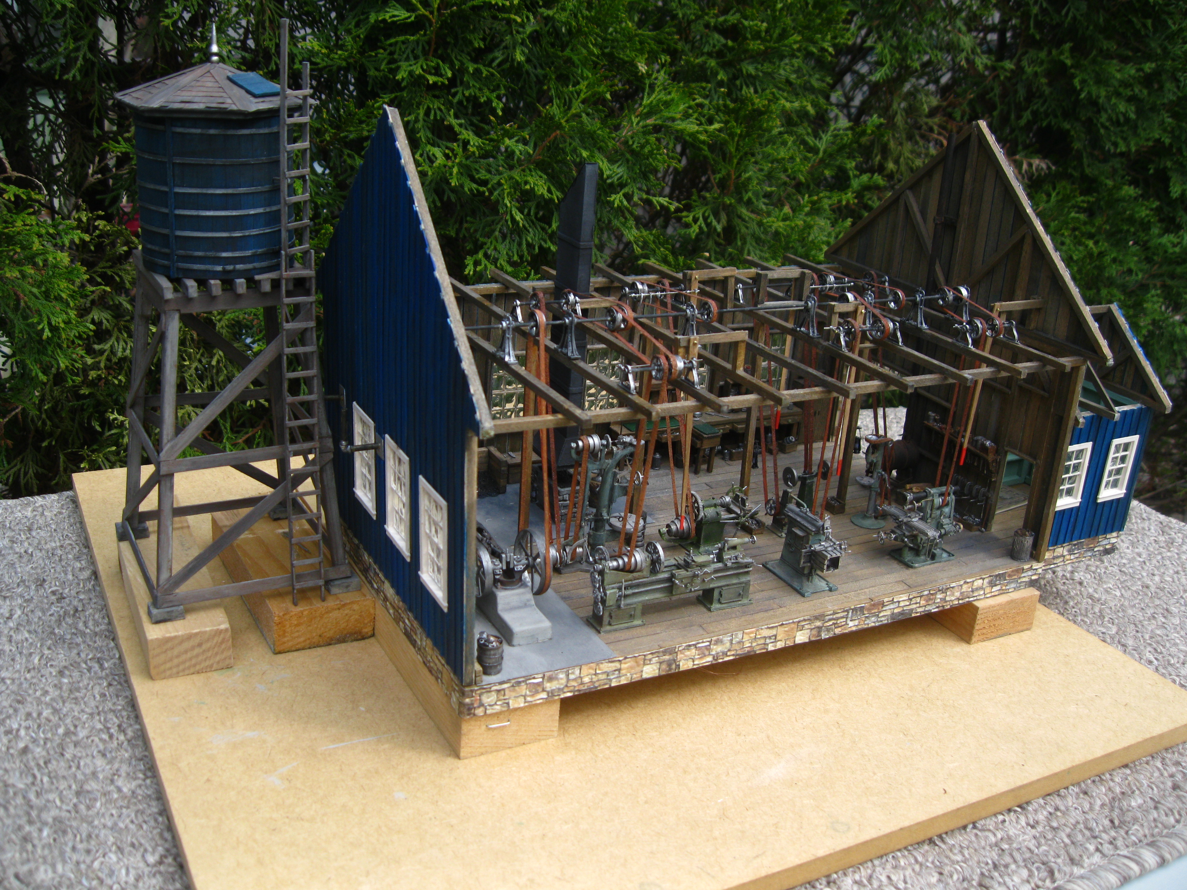
Rob also snapped this image of the log dump end of the sawmill diorama down in my basement.
I still have to add some tree stumps in and around the scene.
And...here is a later shot I snapped from the delivery end of the sawmill...with a single tree stump noticeable off to the right
A lower angle view.
The team of horses get a well-deserved break after hauling the log wagon down into the log dump area.
Rob built the stiff leg derrick from a Crow River Products offering.
I constructed the twin drum hoisting engine and its accompanying inclined oscillating steam slewing engine; both offerings from Crow River Products.
Eventually I will create blog entries on the construction of all these machines.
The Russell Hi-Way patrol grader is a kit available from Wiseman Model Services.
The oxen come from Berkshire Valley Models.
Berkshire Valley offered up the farmer's wagon and team of horses.
An outdoor shot.
Doug gave a seminar to the Rideau Township Historical Society on lumbering in Eastern Ontario at the turn of the century.
The model proved to be a valued asset to his power point presentation.
That's Rob in back with his arms folded.
The fifty or so audience members were 'gob-smacked' by the level of the modelling!
That's Doug in the middle chatting it up with Bruce on the right and an unknown lad on the left.
Doug, Rob & I fielded many questions on how a sawmill works and on the various modelling techniques utilized in completing the diorama.
Following Doug's presentation, the model came back to my home where I added a few more items such as the wood pile and the wheelbarrow filled with sawdust.
Keep in mind that Doug didn't want sawdust strewn all over the sawmill floor as he wanted to keep it clean for educational purposes.
Yes, there would most likely be sawdust in every nook & cranny, but Doug tells us that a teenager may have been paid a pittance to sweep the mill floor at the end of each shift!
I also added a few tree stumps which you can see in the top left corner of the image and a lad who would be cutting the wood into scraps to fit in the boiler's door.
Up on the log ramp where the ladder is located to the left you see another worker about to hose down the logs as they roll onto the carriage.
His water supply is the elevated tank beside its pumphouse.
The water tank also supplies water to the boiler through the elevated piping.
Yes, even a little O-scale wheelbarrow can add so much to the scene.
Filled with sawdust.
Doug sent a black and white image from a logging book to the gentleman who owns Mini-Prints as Doug wanted a well-dressed O-scale figure to play the role of Liam Hicks, the owner of the mill.
The gentleman at Mini-Prints took the 2D image and created a 3D version of the owner of the sawmill for Doug.
Before I painted the Liam Hicks figure I first painted all clothing black then drybrushed white atop to let all of the amazing details 'pop'.
Finally I added washes of colours which you can see in the next image.
This is an image Rob took of Liam Hicks, on the right, which appeared on the cover of the NMRA Mail Car magazine which is the newsletter of the St. Lawrence Division.
Doug, Rob & I wrote a six part series article detailing the construction of our build.
Part Five appears in this issue from the month of November.
To see and read Part Five, simply 'copy and paste' the web address below into your computer's browser.
https://sld-nmra.ca/wp-content/uploads/mailcar/2025_11_high.pdf
Part Four of our article appears here in the September issue.
(Image of CP Railway Bridge over the Rideau River at Merrickville, Ontario taken by Lorne Munro)
https://sld-nmra.ca/wp-content/uploads/mailcar/2025_9_high.pdf
Part Three
(Image of East Broad Top machine shop taken by Stan Conley)
https://sld-nmra.ca/wp-content/uploads/mailcar/2025_3_high.pdf
Part Two
(Image of diorama built by me for my late friend Mike Rozeboom with Mike's CP E8 #1801 passing the engine facility with photo taken by my friend Mike Rozeboom)
https://sld-nmra.ca/wp-content/uploads/mailcar/2025_1_high.pdf
Part One
(Image of the coal dealership I built for Doug after he had started the building on the left which I completed)
https://sld-nmra.ca/wp-content/uploads/mailcar/2024_11_high.pdf
Part Six to come soon!
This was the poster for Doug's speech.
For transport purposes, the two modules are actually quite lightweight.
Here I have them resting atop foam my wife, Lisa, provided.
They are being taken to the Ottawa Valley Associated Railroaders dinner meeting to be shown on the display table there.
A lamp offers ample lighting for the combined diorama.
The lamp actually has a handful of light settings to choose from!
For the setting at the OVAR dinner meeting I pushed the date up a couple of decades to circa 1920.
This allowed me to introduce the Linn Half Truck and the Ford Model TT Truck onto the scene!
Again...many folks had many questions regarding the model and all aspects involved in its construction.
Some 85 members attend our monthly dinner meetings.
For Doug, Rob & me it is always fun to share our modelling projects with the greater railroading community!
In this video we are back in my basement and Doug is explaining to another of our model railroad friends, Jeff Hill, the workings of the log carriage.
To engage the video click on the white arrow in the center of the picture two times, once, then pause, then again.
Yet another video explanation.
Continued explanations from Doug as seen in this video effort.
Funnily enough, one of my favourite aspects of the build was the retaining wall you see at the extreme right of the diorama which holds back the land from the sloping roadway down into the log dump!
Here is a closer look at the retaining wall.
You'll note the trees stumps now in place as well as the sawmill worker carrying the peavey.
Initially, the worker was actually holding a sledgehammer which I cut off.
I then split the peavey in half and glued it to his hands on either side with the handle of the sledgehammer remaining in place between his two hands and painted silver.
Video of the log dump area showcasing the road grader being pulled by the team of oxen among many other items.
To create the oxen handler's 'goad' which assists him in directing the team of oxen I simply used an old guitar string!
Another video of the log dump area.
Final video of the diorama.
I'm posting this entry at 6:00 PM on October 31st.
It's that time when the witch gets out her flying broom...
...and the black cat arches its back......so-o-o...Happy Haunted Halloween!
Here's Doug on the left of the image, Rob on the right and little ole me in the middle!
Hey, thanks so much for checking in on this latest blog entry showcasing the fun Doug, Rob & I have had working as a team on this amazing project!
In future entries I will share with you more detailed notes from the various aspects of this build.
I will intersperse other builds I have been working on in between the various developments on the sawmill or previously completed projects that I have yet to blog about.
All the best, Mike Hamer,
Ottawa, Ontario, Canada


.JPG)
.JPG)